Technical Docs
GRBL AIO – Coolant Output
07
Jan
Jan
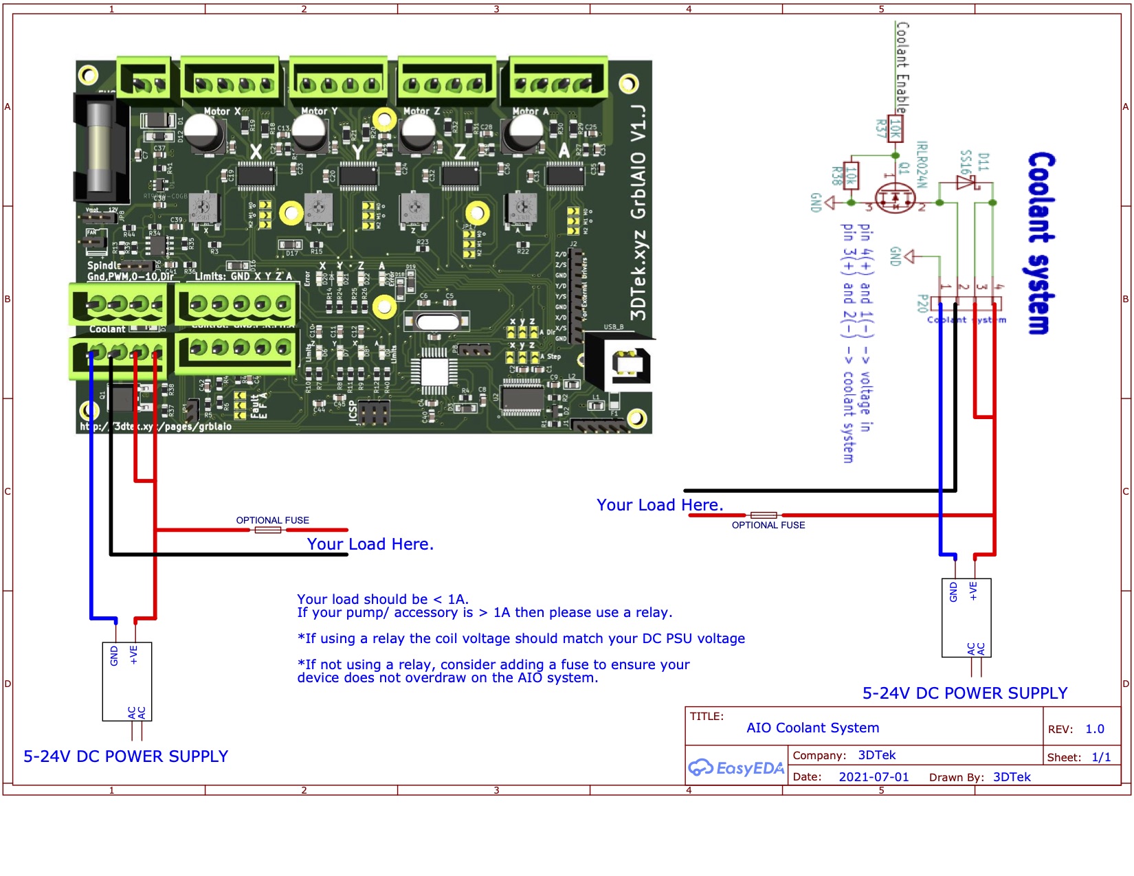
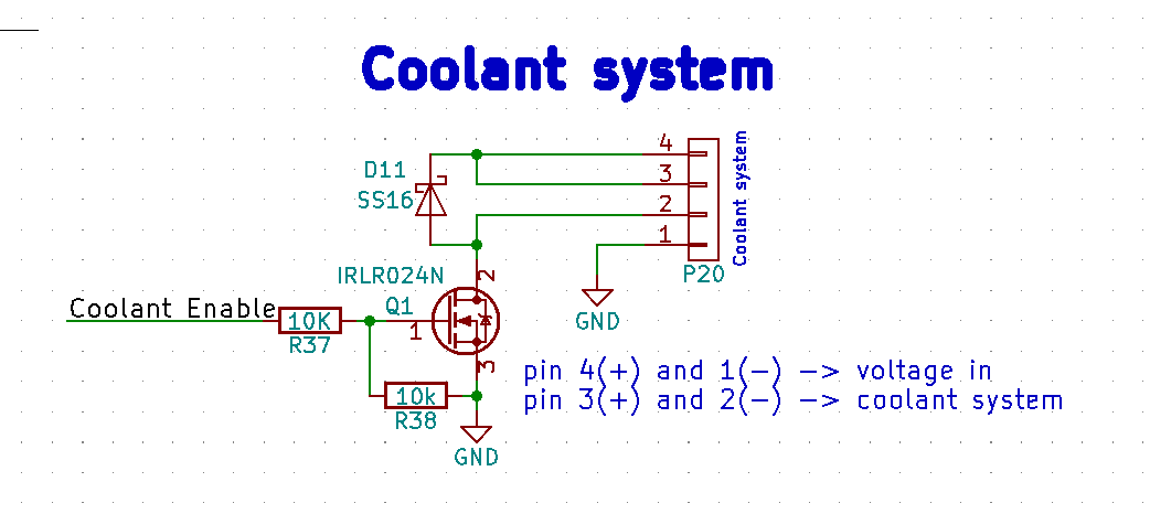
Connecting a Pump or other accessory to the GRBL-AIO Coolant Output.
Notes:
- The coolant output is for switching low voltage & low current DC circuits.
- You should be switching a relay if possible rather than powering your accessory via Coolant Pins 2 & 3.
- On occasions where your accessory requires less than a few amps then you may power it directly without a relay.
- You should connect the DC +ve to both pins 3 & 4 as shown in the circuit diagrams below.
- The Coolant control pin that is switched by the AIO is the GND which is on Pin 2.
Your Circuit.
- Your relay should have a constant connection to the +VE of the power supply.
- Its negative connection should be connected to Pin 2 on the Coolant Output port of the AIO. It is this GND side of your relay’s coil that it’s going to be switched on by the AIO.
GCode Control of Output
- M7 – turn mist coolant on. (Not used unless you have specifically reprogrammed the board)
- M8 – turn flood coolant on. (Shorts Pin 2 to GND)
- M9 – turn both M7 and M8 off. ( Pin 2 disconnected from the ground)